|
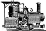
Byers locomotive builder's photograph (ex. libris
Susan Parker).
(Click on image for large 6000 pixel wide
version - c. 2.4 MB jpeg file - opens in new window.)
The Byers 0-4-0 locomotive is an interesting little industrial
engine capable of useful work on both standard or narrow gauge track, and can
negotiate very tight radius curves due to the extremely short wheelbase.
Motive power is provided by a pair of vertical "bottle" style
steam engines, more commonly used in stationary power plants, and a geared drive
to both front and rear axles.
Modelling the Byers Locomotive
I
have two projects based on this locomotive.
A small scale live
steam locomotive in 16mm to the foot scale to run on 1-3/4" (45mm) Gauge 1 or G
scale track. This is to be a "fun" loco and will be a "look and feel" rather
than "exact in all respects" model. An electric version is also possible. Part
of the interest in this scale is that it should be possible to make something in
a relatively short period of time (hopefully months rather than years).
A large scale live
steam locomotive to run on 4-3/4"or 5" gauge track with inside wheel sets,
or 7-1/4" or 7-1/2" gauge track with outside wheel sets which the geared drive
enables one to do easily. The concept is to
have a "run anywhere" locomotive that can fit in the trunk of even a small car
and will still be powerful enough to pull a couple of adults.
Follow the above links for more information.
 Elk
Fire Brick Co Elk
Fire Brick Co
A Byers locomotive at work c. 1946 (images: Tom Crawford collection) .
The Elk Fire Brick Co.'s aptly named "Dinky" locomotive was used
for about 50 years to haul clay wagons at the St. Marys plant in northwestern
Pennsylvania.

Engineering News article - 21st May 1896
A Geared Locomotive for Contractors' Use.
The contractors' locomotive is a very important item of
the plant for many engineering works, quarries, brick years, etc., and
whilst fitness of finish and economy in operation are not important
requirements, strength of parts and attachments is exceedingly important
to enable the engine to work regularly over a very rough track and to
withstand the shocks and rough handling to which it is inevitably
subjected. In a majority of cases the engines used by contractors are
ordinary locomotives of small size, with piston rod connected directly
to the driving wheels by a connecting rod, but in recent years geared
locomotives have shown such advantages as to come into favor. We show
herewith a geared locomotive designed for contractors' use, and built by
the John F. Byers Machine Co. of Ravenna, O.
This locomotive is a four-wheel tank engine, and has
heavy cast-iron sectional frames, in which are formed the guides for the
axle boxes, and which serve to add to the adhesion weight of the engine.
The wheels are 24 ins. in diameter, and are placed inside the frame for
a track of 36 ins. gage, and outside for standard gage. They are of cast
iron, with chilled treads. Upon the middle of each side frame is mounted
a vertical inverted engine, driving a main shaft, which carries and
driving pinion A. This pinion drives two gear wheels B, B, on a
countershafts, which in turn drive the two pinions C, C, on the axles of
the carrying wheels. It is plain spur gearing, back geared 3 to 1, three
revolutions of the engine giving one revolution of the axles. The gear
wheels are cast with solid webs and wide faces, and the pitch of the
teeth is 1 1/2 ins. The countershafts are 2 7-16
ins. diameter, carried in bearings on a transverse frame or bedplate,
which is bolted to the side frames. The main axles are of steel, 2 15-16
ins. diameter, with large bearing carried in oil boxes. The leading axle
has side-bearing bars D, D, which rest on bearing boxes on the axle E,
E, and these bars carry the transverse equalizer F. This arrangement
allows sufficient vertical play in the leading main bearing, and also
effects such a distribution of the weight that the engine will ride
steadily over any ordinary inequalities in the track, and will pass
easily around curves of 25 and 30 ft. radius.
The boiler is of T shape, with a circular firebox in the
vertical leg and tubes in the horizontal barrel. This barrel is entirely
filled with water, the water level reaching up into the vertical leg,
and steam is taken from the upper part of this leg, which serves as the
steam dome. The shell is lagged and jacketed in the usual way. The
exhaust pipes run full size to the exhaust nozzle in the smokebox, and
discharge into a petticoat pipe of the usual pattern. The vertical
extension of the exhaust pipes downwards on the outside of the smokebox,
as shown in the general view, is for the purpose of a drip, and the
lower end of each extension is provided with an opening 1/8
in. diameter, which is left permanently open. In the later engines the
exhaust is run from the cylinders directly underneath the boiler, and
thence by a single pipe to the smokebox, a single drip pipe with
permanent opening being provided. The sandbox and bell are mounted on
the boiler barrel, and the fitting include a glass water gage, water try
cocks, two injectors, etc.
The engine is provided with a friction brake, shown in
the side elevation, which is placed on the rear countershaft. It
consists of two cup-shaped disks G, G, faced with wooden friction blocks
H, H. These disks are attached to two yokes J, J, which in turn are
moved in line with the countershaft by means of the threads on the
operating shaft K. The brake is applied by moving the disks G, G against
the center disk L, which is keyed to the countershaft. The yokes J, J
and the disks G, G work lose on the shaft, but are fastened at the lower
or forward end of the yokes J, J to the transverse bedplate., This brake
is operated by a horizontal hand wheel M, and bevel gear N. It is
powerful and sensitive and very easily handled.
The drawing show only the iron frames, the wooden
footboard and front end supports being omitted. The front and back cross
frames have been changed somewhat from the form shown in the photograph,
but the arrangement of the engine, main shaft, countershafts, gears,
driving wheels, etc., is the same in all the machines. These locomotives
are said to give a steady drawbar pull, and to be capable of hauling and
train load of 250 tons (including weight of cars) at a speed of six to
eight miles per hour on a straight and level track. Their short
wheelbase enables then to pass the very sharp curves usually to be found
on contractors' track and industrial railways. Four of these locomotives
have been built thus far, and three of them are in service, being used
by the Casparis Stone Co., of Loansport, Ind.; the Buffalo Cement Co.,
of Buffalo, N. Y., and W. J. Murray, contractor, of New York city. The
general dimensions of the engines are given in the accompanying table: |
General Arrangement Drawings.
Locomotive Plan and Side Elevation Drawing (ex. libris
Susan Parker).
(Click on image for large 5700 pixel version - c. 375 KB
gif file - opens in new window.)
Technical
Specification
Contractors' Geared Locomotive
|
| Driving wheels, diam |
24 ins. |
| Journals, driving axles |
2 5-16 x 4 ins. |
| Axles, diam |
2 15-16 ins. |
| Main shaft, diam |
2 1/8 ins. |
| Countershaft, diam |
2 7-16 ins. |
| Wheelbase |
3 ft. 4 ins. |
| Length over all |
12 ft. 2 ins. |
| Width over all |
6 ft. |
|
| Weight in working order |
11,000 lbs. |
| Full coal capacity |
250 lbs. |
| Full water capacity of tank, |
100 gallons 834 lbs. |
| Allowed for water in boiler, |
180 gallons 1,500 lbs. |
|
| Cylinders |
5 1/2 x 7
ins. |
| Distance c. to c. |
4 ft. 1 in. |
| Piston rod, diam |
1 in. |
|
| Valve Gear |
Link Motion |
| Steam ports |
9-16 x 4 1/2 ins. |
| Exhaust ports |
1 x 4 1/2 ins. |
| Lap of valves |
5-16 in. |
| Lead of valves |
1-16 in. |
| Max. travel of valves |
2 ins. |
|
| Boiler; type |
Tee |
| Vertical leg |
32 x 60 ins. |
| Barrel |
26 x 64 ins. |
| Tube sheet and barrel plates |
1/4 in. |
| Height from rail to centre line |
3 ft. 9 ins. |
| Length of smokebox |
1 ft. 8 ins. |
| Working steam pressure |
120 lbs. |
|
| Firebox |
Circular |
| Diameter inside |
28 ins. |
| Depth inside |
26 ins. |
| Side plates |
5-16 in. |
| Crown sheet |
3/8 in. |
| Grate area |
4 sq. ft. |
| Staybolts, diameter |
3/4 in. |
| Water space, width |
2 ins. |
|
| Tubes; material |
Steel |
| Number |
32 |
| Diameter, outside |
2 ins. |
| Length between tube plates |
6 ft. 0 ins. |
|
| Heating surface - |
| Tubes |
88 sq. ft. |
| Firebox |
14 sq. ft. |
| Total, with exterior tube area |
102 sq. ft. |
|
| Exhaust nozzle, diam |
1 11-16 ins. |
|
| Smokestack, smallest diam |
8 ins. |
| Height |
3 ft. 4 ins. |
| Height from rail to top |
8 ft. 2 ins. |
|
| Tank capacity |
100 gallons |
| Coal capacity |
250 lbs |
| Brake Friction disk, |
operated by hand. |
|
| Gearing: |
| Driving pinion; diam., |
5 13-16 ins.; |
number of teeth 12 |
| Intermediate pinion; diam., |
12 ins.; |
number of teeth 25 |
| Axle gear wheel; diam., |
17 9-32 ins.; |
number of teeth 36 |
|
|
Photograph, description, drawings and table
scanned/transcribed by myself from the original Engineering News article of the
21st May 1896 - Pages 342 & 343
Byers Engines
Byers produced a wide range of
single and twin cylinder stationary engines. Their railway locomotives were
presumably a diversification project as only about a half dozen were produced
(see the
Geared Steam Website - Byers Owner Roster)
and these made substantial use of their standard stationary engine components.
The locomotive engine was based
on their 16 horsepower twin cylinder stationary engine, and had the valve gear
positioned outwards on either side (unlike their standard stationary twin).
Cross section detail and parts description of a Byers Vertical Steam
Engine (SP).
Illustration of Byers vertical steam engine and boiler, and size and
specification of double cylinder engines (SP).
( The scans for these two Byers pages 4 and 38 were sent to me
after this page was initially put up and provide a lot of useful additional
information which is much appreciated.)
Information Source
I was fortunate in finding an
original copy of the Engineering News article contained in the 1896 journal (Jan
to June). It was an eBay purchase and although it cost me USD150 to buy and ship
to England I felt it was worthwhile to get the original pages to scan. I wasn't
aware of the picture at that time, so I am even more pleased to have that for
the additional information.
Original Byers Locomotive Article - 21st May 1896 -
Pages 342 & 343 (ex. libris Susan Parker).
(Click on image for large 1000 pixel version of page 342 -
c. 1.3 MB jpeg file - opens in new window.)
Unfortunately the bound
journal does not include the advertisements, so I have linked this image from
the Geared
Steam website.
Engineering
News Advertisement, January 1896 - Geared Steam Image.
(N.B. not January 6th as issue dates were on the 2nd, 9th, 16th, 23rd or 30th of
that month).
Additional References & Links
|
|
|
|
|
|
|
|
|
Link images in this section are linked from
their respective websites - please let me know if they disappear. |
|