Temperature compensated Bias from constant current source.
Temperature compensated V-Bias Circuit.
V-Bias from a fixed voltage regulator.
V-Bias Circuit.
Representative General Circuit.
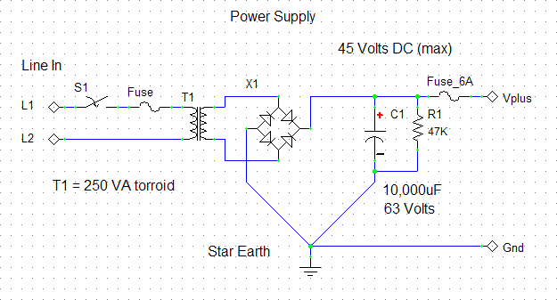
This is the only part of the amplifier that has potentially lethal voltages. Please take care when assembling and ensure that all live mains connections are covered so that they cannot be accidentally touched by hand or with a tool. The power supply may be built into a separate enclosure. Additional information will be added in time. The information contained here is given in good faith but I cannot take any personal liability for the building or use of any of the items described. This page last modified on: 2nd March 2005 All information, drawings and images Copyright © 1995 - 2005 Susan Parker unless otherwise credited. |


