Tube first switch on.
Fig 1. General 6C33C Line Driver Schematic.
Breadboard Tube Line Drive Amplifier 600 ohm balanced input from E-Mu 1212M soundcard, balanced XLR output to power amplifier.
First Test: 1 kHz THD+N at 4 V rms into 600 ohms < 0.08%
THD v Frequency at 4 Vac RMS into 600 ohms (HP 8903B - No HF low-pass filter).
% Distortion and Vac Output Level Graph - Bandwidth is 25 Hz to 70 kHz (63 kHz shown). Supply at 250 mA and 400 mA curves, plus mosfet version of PP line amplifier for comparison (using same transformers).
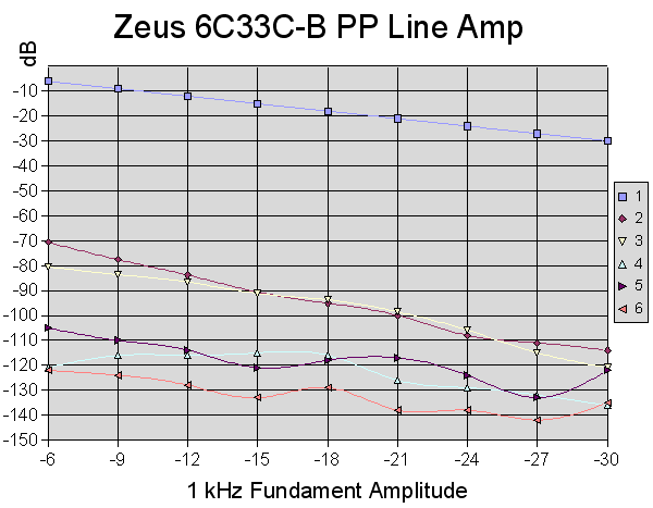
Harmonic Amplitude v. Signal Level (E-Mu 1212M + FFT).Note: measurements below -120 dB are limited by the PC / sound card performance, see loopback test at bottom of page.
Harmonic amplitude v. signal level at 1 kHz.
Harmonic amplitude v. signal level at 10 kHz.
Note: Distortion levels are mostly dependant on bias current, not on B+ voltage. Operating at a higher B+ voltage, e.g. +90 volts, does not make any
substantive improvement in performance, Tests for B+ Supply Voltage / Current and Vg Bias
Harmonic Amplitude v. B+ Supply Volts at 400 mA B+ Current (E-Mu 1212M + FFT). WITH
Vg Bias v. B+ Supply Volts to Obtain 400 mA B+ Current.
Harmonic Amplitude v. B+ Supply Current at B+ 65 Volts (E-Mu 1212M + FFT). WITH
Vg Bias Voltage v. B+ Supply Current at B+ 65 Volts.
Distortion v Load
Harmonic Amplitude v. Load (at B+ 65 Volts, I = 400 mA). Constant input amplitude - note small variation in fundament level. N.B. Measurements at or below -120 dB vary during testing.
Percentage THD v. Load (at B+ 65 Volts, I = 400 mA).
WINaudioMLS 192 kHz, 1 million point FFTs( Note intermodulation products on 1 kHz fundament and it's harmonics.)
1 kHz input at -6db 0.071% -62.96db THD, Display range 45hz-96khz.
1 kHz input at -6db 0.071% -62.96db THD, Display 850hz-20khz; close-up showing intermodulation.
Input mute, peak signal 50Hz 64.6db display range 45Hz-96kHz
Distortion and Output Graph - Bandwidth is 25 Hz to 70 kHz (63 kHz shown).
E-Mu 1212M Loopback Comparison
E-Mu 1212M loopback, 1 kHz input at -6db 0.0017% THD, Display range 45 Hz to 96 kHz Note HF rise above 50 kHz
Design by: Susan Parker, MIEE.The information contained here may be used to construct one set of amplifiers specifically for personal NON commercial use only. N.B. Personal liability disclaimer applies. ALWAYS take extra care when prototyping and testing any items connected to mains line voltages or that use high voltages or currents in the circuit. ALWAYS fuse power supplies appropriately. 6C33C Power Tubes / Valves run HOT - Please be careful. N.B. My prototype breadboard is for testing purposes only and is not a suitable method of construction for general use. This page last modified on: 4th May 2005 All information, drawings and images Copyright © 1995 - 2005 Susan Parker unless otherwise credited. |


